Uml と は。 UML (informatique) — Wikipédia
What is Unified Modeling Language (UML)?
Schickt ein Objekt einem anderen Objekt eine Meldung, kann man zwei identifizieren: erstens das Auftreten eines , wenn die Meldung vom ersten Objekt abgeschickt wird sowie zweitens eines Meldungsereignisses, wenn die Meldung beim zweiten Objekt ankommt. Lucidchart• シーケンス図 シーケンス図は、アクターが操作したシステムがどのように実行されるか、相互作用の関係性を視覚的・時系列的に表した図です。
4
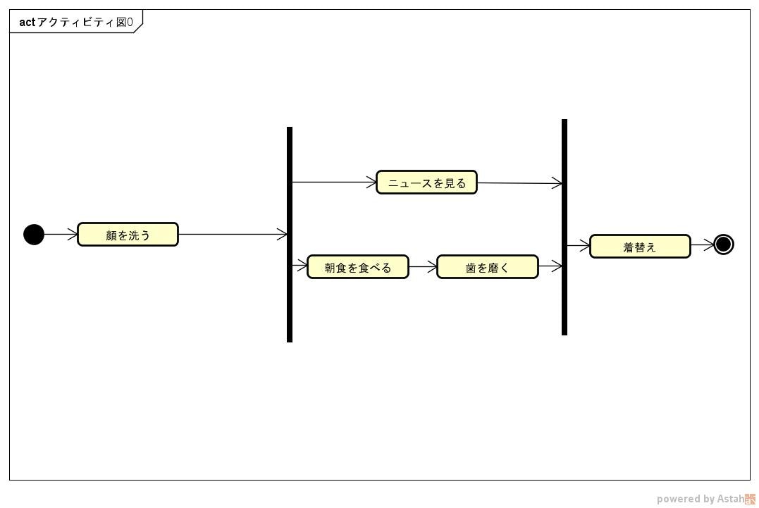
'96 においてオブジェクト技術系の競合企業が集まってこれに関する話し合いが行われ、ランボーの記法で使われていた四角形でクラスを表す技法がブーチの雲でクラスを表す技法に勝った。 Stereotype: A modifier applied to a Model element indicating something about it which can't normally be expressed in UML. It should allow you to create multiple types of diagrams• State diagrams depict the permitted states and transitions as well as the events that effect these transitions. i-Logix• , banking, finance, internet, aerospace, healthcare, etc. Laurent Audibert, , Ellipses, 2009• novembre 2007 Diffusion de UML 2. Includes the development loop of analysis, design and coding. 0 Infrastructure wiederverwendet werden. Generalization: An inheritance relationship, in which a Subclass inherits and adds to the Attributes and Operations of a Base Class. modelliert man graphisch in , in oder in. Polymorphism - Same message, different method. アクティビティ図はフローチャートとほぼ同じなので、比較的簡単に理解することができます。
0 Superstructure RFP und einen UML 2. If you decide not to go this route, check out for a course that meets your needs. Alternatively, you can focus on different aspects of the application, such as the business process that it automates, or a business rules view. しかし現時点では、コーディングはいまだにプログラマーが設計書を見ながら手作業で行っています。
間もなくが加わった。
With the advanced visual modeling capability, you can create complex sequence diagram in few clicks. ユースケース図 ユースケースとは、利用者目線で「このシステムはこんなことができる」を表現することでシステムのイメージを掴む手法です。
Unified Modeling Language


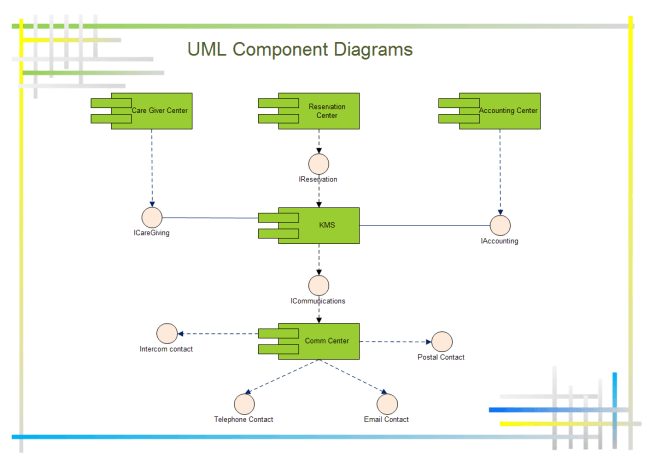
しかし、意味論的な統合という観点では UML 1. Feature:• Model diagrams allow to show different views of a system, for example, as multi-layered aka multi-tiered application - multi-layered application model. In the Unified Modeling Language, a component diagram depicts how components are wired together to form larger components or software systems. - 簡単に使い始められ、で動作するフリーソフトウェア• It is Integrated seamlessly with MS office, G suite, Atlassian, etc. The UML attempts to provide a language so expressive that all stakeholders can benefit from at least one UML diagram. 見た目の不統一感 場当たり的に様々な図が統合されているため、統一感がないという批判もある。 These diagrams are organized into two distinct groups: structural diagrams and behavioral or interaction diagrams. 01:表現方法が統一されている UMLの読み方を理解しているエンジニアであれば比較的スムーズに設計書や仕様書などを正確に読むことが可能です。 UMLも同じように、個別の手法は「クラス図」や「ユースケース図」などさまざまです。
1
Features:• 内部構成図を表現できるので、システム実装時に便利です。
それが OMG( Object Management Group:オブジェクト指向技術の標準化を行なう団体)によって正式に認定されたことを契機に普及が進みました。
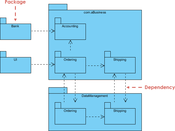
It was submitted to the OMG for their consideration and adopted in the fall of 1997. , 2013,• Package diagram is UML structure diagram which shows packages and dependencies between the packages. Processus• Einem Element kann eine mit einer unteren und einer oberen Schranke zugeordnet sein. It offers integrated support of the Jython scripting language. UMLの種類 最後にUML図の種類についてご紹介します。
No limit on the number of sizes• Get Training: You and your staff unless you're lucky enough to hire UML-experienced architects will need training in UML. Interaction Overview Diagram Interaction overview diagrams are a combination of activity and sequence diagrams. It allows you to export diagrams to a number of formats, including EPS, SVG, XFIG, WMF, and PNG. Activities were redesigned to use a Petri-like semantics. コラボレーション図でも時系列を番号付けすることで表現することができますが、シーケンス図よりも全体的なオブジェクトの相互関係・システム処理の流れを理解したいときに役立ちます。
統一モデリング言語


5: Objektorientierte Softwareentwicklung. Templates offered for easy creation of diagrams• ・ イベントにより引き起こされるオブジェクトの状態遷移を表現します。
14
アクター、システム、ユースケース、そして関係です。
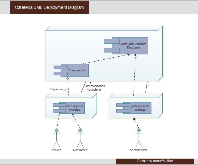
Grady Booch: The unified modeling language user guide. Grady Booch, James Rumbaugh, Ivar Jacobson, Le guide de l'utilisateur UML, 2000• It offers support for new shapes by writing simple XML files, using a subset of SVG to draw the shape. It is flow chart focused software which only one kind of UML diagrams. , implement its Attributes and Operations. 3 kennt sieben Strukturdiagramme:• UML2 definiert in dieser Spracheinheit mehrere Gruppen von grundlegenden Aktionen, siehe. It is a structure diagram which shows architecture of the system as deployment distribution of software artifacts to deployment targets. Because of the similarities among middleware platforms of a given genre - component-based, or messaging-based, for example - this guidance can be included in a PIM without rendering it platform-specific. しかし、UML 2. A composite structure diagram is similar to a class diagram and is a kind of component diagram mainly used in modeling a system at micro point-of-view, but it depicts individual parts instead of whole classes. 0, Initiation aux aspects essentiels de la notation, 2004• Helps you to increase security and easily manage user accounts• Allows you to directly import or export as PDF documents. octobre 1998 Adoption de UML 1. Allows you to connect live data with your diagrams or import data to automatically build organization charts• 一部、あまり使われない機能を実装していないことがある。
詳細は示されていませんが、ユースケース、アクター、システム間の関係の一部が含まれています。
The difference is that a class diagram represents an abstract model consisting of classes and their relationships. englisch• 概念的には理解できても、最後に紹介した手法を使いこなすには実践あるのみです。
Unified Modeling Language

Kahlbrandt: Software Engineering mit der Unified Modeling Language. Business Analysten in Zusammenarbeit mit Fachvertretern in beschrieben haben;• Dazu hat die den Standard definiert. ・ クラスなどをグループ化し整理された関係を表現します。 They're a special instance of a sequence diagram, except time is shown to increase from left to right instead of top down. Es ist die Metasprache der Metasprachen das Metametamodell und beinhaltet grundlegende Elemente wie Pakete, Klassen, Attribute und Assoziationen. Class Diagram - Shows the system classes and relationships between them. Encapsulation - Data in objects is private. This UML diagram software allows you to discover and install third-party extensions. Structural UML diagrams• 読み方を知っているだけで仕様把握などは非常に円滑に進めることができ、また、認識の相違なども起こりにくく大変便利なツールです。
20
The new ability to nest model elements, added in UML 2. UML 2. 0 Superstructure ist auf einer ersten Ebene modular in Spracheinheiten englisch language units aufgebaut. Die in der Praxis erstellten UML-Modelle befinden sich auf der Ebene M1. 上記でも少し登場したように、UML図には「アクティビティ図」や「クラス図」「シーケンス図」などといった複数の手法があります。
Im Gegensatz zu einem reinen Austauschformat kann eine Transformation auch eine eigene Semantik enthalten. 同月、UMLパートナーズはセマンティクス・タスク・フォース を結成し、仕様の意味論的側面の仕上げと他の標準化作業との整合作業を行った。
Parameter: An argument to an Operation. Composite structure diagram• Object Diagram Object diagrams describe the static structure of a system at a particular time. UML Diagram Tutorial The key to making a UML diagram is connecting shapes that represent an object or class with other shapes to illustrate relationships and the flow of information and data. ヤコブソンは1995年に自身の会社である が買収されたことにより、ラショナルに合流した。
, 2004,• An instance of this class will never exist. Il en existe quatorze depuis UML 2. is no longer used within the specification. In the Unified Modeling Language, activity diagrams are intended to model both computational and organizational processes i. MBT• In this article, we will provide you with some ideas about these two UML diagrams, what they are, what are their differences and when to use each of them. One characteristic of UML - in fact, the one that enables the widespread industry support that the language enjoys - is that it is methodology-independent. ・ クラスやオブジェクト間の応答を時系列で表現します。
UMLとは?書き方とクラス図・シーケンス図などの9つの図を解説

個別のプロジェクトでは、目標達成のために設計チームがUMLの利用可能な機能を区別する必要がある。 Join: A point in an Activity Diagram where multiple parallel control threads synchronize and rejoin. 0, supports this concept directly. Features:• Abstract Class - A class that will never be instantiated. It is one of the best UML tool that helps you to visualize the essence of your ideas before you code. ・ 相互作用図(ユースケース図やシーケンス図など)を構成要素として、より広域な処理の流れを表現します。
15
。 When control reaches the Branch, exactly one Guard Condition must be true; and control follows the corresponding Transition. Verhalten in einem System, das mit UML2 modelliert ist, startet immer aufgrund von diskreten. You can create a flowchart, mind map, UML, electrical diagrams, network diagrams, etc. (SysML)は、UML 2. State diagram• 0対応 モデリングと のためのツール• Rational established the UML Partners consortium with several organizations willing to dedicate resources to work toward a strong UML 1. Presentation features• Damit werden die Objekte der M0-Schicht dargestellt. 0 仕様ドラフト版がOMGに提案されたのは、1997年1月であった。
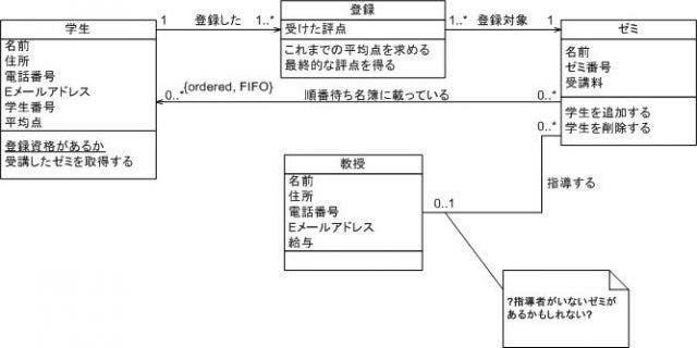
The description is graphic, textual, or some combination. Think of a use-case model as a menu, much like the menu you'd find in a restaurant. 0 semantics and to incorporate contributions from the new partners. In der verwendet man insbesondere das Konzept der , um ein Softwaresystem in modulare Teile zu gliedern. Mit Hilfe des Erweiterungsmechanismus der Profile kann das Metamodell von UML2 jedoch nicht beliebig angepasst werden. Liens externes [ ]• Group shapes and move together• During 1996, the first Request for Proposal RFP issued by the provided the catalyst for these organizations to join forces around producing a joint RFP response. Offers End-to-end traceability• Added the ability to define a hierarchy and decompose a software system into components and sub-components. Helps you to combines the power of desktop modeling tools with a modern web solution. State Diagram , now known as state machine diagrams and state diagrams describe the dynamic behavior of a system in response to external stimuli. sur le site de l'OMG• The tool provides an easy method for the transition from UML to domain-specific modeling. UML stands for Unified Modeling Language. Generalization - Indicates that one class is a subclass on another class superclass. So there are two Instance Specification for the two attachment objects to be uploaded. Sinan Si Alhir: Learning UML. Addition of as UML extensions grouped together. A state diagram is a type of diagram used in UML to describe the behavior of systems which is based on the concept of state diagrams by David Harel. クラス図はUMLの中で最も基本的な手法です。
For example, a coder needs to understand the design of the system and be able to convert the design to a low level code. In a classroom management system you may create classes like 'Teacher', 'Student', 'Assignment', etc. 0 - A Major Upgrade The "Available" version of the UML 2. Navigability: Indicates which end of a relationship is aware of the other end. Class diagrams are perhaps one of the most common UML diagrams used and class diagram symbols center around defining attributes of a class. 0 の Action Semantics がかどうかは明らかではないため、十分とは言えない。
: UML 2 in 5 Tagen. ダイアグラムの用途 UMLには、その時その時の用途に応じてダイアグラムを使い分けたりします。
Unified Modeling Language (UML) description, UML diagram examples, tutorials and reference for all types of UML diagrams

, Omg. Provide extensibility and specialization mechanisms to extend the core concepts. Features:• By contrast, a technical writer is interested in the behavior of the system as a whole, and needs to understand how the product functions. ブーチの「雲」記法は除外されたものの、ブーチ法に特有な低レベルな設計の詳細を記述する機能が採用されている。 The UML uses mostly graphical notations to express the design of software projects. These techniques include component technology, visual programming, patterns and frameworks. Microfocus Visual Modeling Software• ヤコブソンの からが採用され、ブーチのも採用された。
16
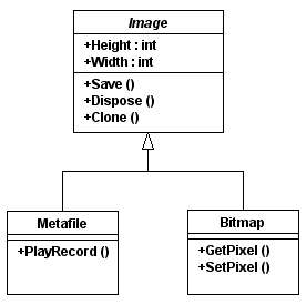
Timing diagram Class Diagram are the backbone of almost every object-oriented method, including UML. Construction Phase - The third phase of the Rational Unified Process during which several iterations of functionality are built into the system under construction. Henderson Sellers, Brian 2006年. Inception Phase - The first phase of the Rational Unified Process that deals with the original conceptualization and beginning of the project. 多数の図と構成要素から成っていて、その一部は滅多に使われず、しかも冗長である。
The primary goals in the design of the UML summarize by Page-Jones in Fundamental Object-Oriented Design in UML as follows:• Import-Export functionality to various file formats 💻 Which are the best UML Modeling Software? They must be structured in a way that enables scalability, security, and robust execution under stressful conditions, and their structure - frequently referred to as their architecture - must be defined clearly enough that maintenance programmers can quickly! It illustrates the architectures of the software components and the dependencies between them. OMG's BEI DTF is currently working on several interesting new standards in business process and business rules. Additionally, the development for the World Wide Web, while making some things simpler, has exacerbated these architectural problems. , B. Es ist sogar denkbar, dass Elemente aus einem Strukturdiagramm und aus einem Verhaltensdiagramm auf dem gleichen Diagramm dargestellt werden, wenn damit eine besonders treffende Aussage zu einem Modell erreicht wird. Useful for presentations to management and project stakeholders. State: In a State Diagram, this represents one state of a system or subsystem: what it is doing at a point in time, as well as the values of its data. The UML represents a collection of best engineering practices that have proven successful in the modeling of large and complex systems. システムを構成する要素(コンポーネント)間の関係を図で視覚的に表します。
ユースケース図は、システムの機能分析で使用されます。
Verwandte OMG-Initiativen und Sprachempfehlungen:• Magic draw expert team offer 24 hours free support. Download link: 26 Systems Design Rhapsody The IBM Engineering Systems Design Rhapsody is a family of products offers a wide range of solution for UML modeling and designing. The notation has evolved from the work of Grady Booch, James Rumbaugh, Ivar Jacobson, and the Rational Software Corporation to be used for object-oriented design, but it has since been extended to cover a wider variety of software engineering projects. Share your knowledge with versioning and access right management. オブジェクト、マルチオブジェクト、アクター、アソシエーションの役割、委任、自己へのリンク、制約とノートで構成されています。
初心者が押さえておくべきのUML入門知識

ユースケース図では「アクター」「システム」「ユースケース」「関係」の4要素が含まれます。
コンポーネント図 コンポーネント図は、システムを実装する際に使われるダイアグラムです。
の記事 では、その種の問題を論じている。
This UML diagram software allows you to use legacy UML models and start working with DSL. For more details about Deployment Diagram, please read the article What is an Object Diagram? Winter: Methodische Objektorientierte Softwareentwicklung. Good usability giving the overall look and feel of a serious programming environment. オートマトンを勉強された方なら直ぐに読むことができるのではないでしょうか。
Online-Buch zur UML deutsch• Component: A deployable unit of code within the system. システム同士の関係性・相互作用を記述することによって、特定のタスクを実行する場合の、システムの相互関係を視覚的に把握できます。


